


DXA-205 DC-1.5 MHz Digital Lock-in Amplifier
Applications:
Scanning Microscope: AFM, STM, SPM
Materials Science: Carrier mobility, Carrier density, Hall effect, Ultrasonic materials
Transport Measurement: Conductivity measurement, Impedance measurement
Noise Represents: Noise density, Cross-correlation measurement
Optical Experiment: Spectral analysis, Spectral measurement, THz measurement, TDLAS
Sensor Measuring: Gyroscope, Photoelectric sensor, Resonator, Accelerometer
Magnetic Sensor: SQUIDs, NV color center, Atomic Magnetometer, VSM
Biomedical: Microfluidic
| Input Signal Channel | |
| Input Mode | Voltage: Single-ended or Differential |
| Current: Single-ended | |
| Full-Scale Sensitivity | 1 nV to 5 Vrms |
| Range Levels | 2mV to 5V, total 7 levels |
| Input Coupling Mode | DC or AC coupling |
| Input Impedance | 10 MΩ || 25 pF (Voltage) |
| 100Ω or1 kΩ (Current) | |
| Input Shield Grounding | Grounding or 10 kΩ floating |
| Dynamic Reserve | >130 dB |
| Gain Accuracy |
0.5% typical, 1% max |
| Input Voltage Noise | 3.5 nV /√Hz(f ≥ 1 kHz) |
| 2.5 nV /√Hz(f ≥ 10 kHz) | |
| Input Current Noise | 20 fA /√Hz(f = 97Hz) |
| ADC Bit | 24 bit |
| Output Signal Channel | |
| Frequency Range | DC – 1.5MHz |
| Frequency Accuracy | 2 ppm + 1 μHz |
| Frequency Resolution | 1 nHz |
| Sine Amplitude | 0.1 μVrms to 5 Vrms |
| Accuracy | 0.5% typical, 2% max |
| Resolution | 0.1 μVrms |
| Driving Current | ± 80 mA max |
| Temperature Stability | <200 ppm/℃ |
| Output Impedance | 50 Ω |
| Adjustable DC Offset | -5 VDC to 5 VDC |
| Synchronous Output | 3.3V TTL/CMOS level |
| output impedance 50 Ω | |
| Additional Features | AM/FM/PM modulation output |
| DAC Parameter | 16 bit, 32 MSPS |
| Reference Signal Channel | |
| Reference Channel Number | 2 |
| Reference Signal | Frequency Range: 10 μHz – 1.5MHz |
| Supported Waveform: Square or sine wave | |
| Input Impedance: 1 MΩ | |
| Reference Levels | Square: 3V |
| Sine Frequency: > 1 Hz; 300 mV < Vpp < 10 V | |
| Phase | Resolution: 1.0 μdeg |
| Phase Error: ±0.5 deg typical, ±1 deg max | |
| Temperature Drift: < 200 ppm/℃ | |
| Harmonic Detection: 1-10000F (nF < 1.5 MHz) | |
| Acquisition Time | Internal Reference: Instantaneous acquisition |
| External Reference: 10 or 100 signal cycles | |
| Oscillator | |
| Oscillator Number | 2 |
| Oscillator Parameters | Accuracy: 0.3 ppm |
| Temperature: Stability 0.5 ppm/℃ | |
| Aging Rate: <1 ppm/year | |
| Phase Noise: -145 dBc/Hz (@1kHz) | |
| Demodulator | |
| Demodulator Number | 8 |
| Demodulator Bit | 64 bit |
| Time Constant | 100ns - 3ks |
| Measurement Bandwidth | 50 μHz – 1.6 MHz |
| Filter Slope (dB/oct) | 6, 12, 18, 24, 30, 36, 42, 48 |
| Synchronous Filter | <1000 Hz effective |
| Auxiliary Inputs/Outputs | |
| AUX Input | Function: 4-channel input |
| Amplitude: ±10V, 0.1 mV resolution | |
| Input Impedance: 1MΩ | |
| ADC: 16 bit, 150 kSPS | |
| AUX Output | Function: 4-channel output |
| Amplitude: ±10V, 0.1 mV resolution | |
| Driving Current: ±30 mA max | |
| DAC: 16 bit, 500 kSPS | |
| Communication Interfaces | |
| RS-232 | DB-9 female interface |
| USB2.0 | 480 Mbpshigh-speed interface |
| Ethernet | RJ45-1000Mbps |
| WIFI wireless etwork interface | |
| GPIB | IEEE-488.2interface |
| Others | |
| Power Supply | Voltage: 220-240 V AC; 100-120 V AC(optional) |
| Power: 50 W typical, 70 W max | |
| Power Noise Suppression | 70dB@1MHz |
| Dimensions | 448mm×532mm×148mm |
| Weight | 12 kg |
Oscilloscope
Oscilloscope function with 2 signal channels, selectable signal input, reference input, signal output, auxiliary input and output signals, with a variety of triggering methods, for the user real-time display of time domain signals. Maximum 65536 sampling depth, adjustable sampling time 65us - 1s.

PID Controllers
The DXA-205 has an internal independent 2-channel digital PID controller with a maximum sampling rate of 4 MSPS. The PID controller is closely linked with the lock-in amplifier, controlling the output signal's amplitude, phase, frequency, and other signals based on the measurements from the demodulator, achieving precise control of multiple parameters.

Parametric Scanner
The parameter scanner provides users with convenient and fast scanning for instantaneous plotting of frequency response, amplitude response and other curves, and offers single or cyclic scanning modes.

FFT Spectrum Analyzer
FFT spectrum analyzers analyze the frequency domain information of a signal based on the waveform captured by an oscilloscope. Depending on the sampling rate, the frequency resolution of the spectrum analyzer is approximately 1Hz - 31kHz.

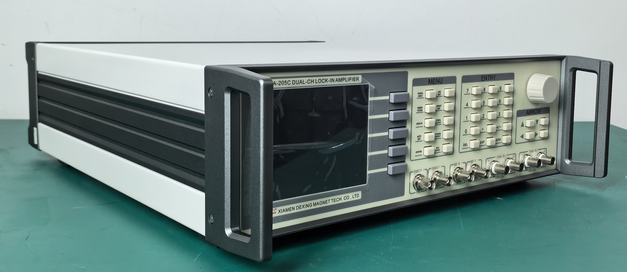
DXA-205C DUAL-CHLOCK-INAMPLIFIER
Input noise as low as 2.5nV/√Hz;
Input range 1nV to 5Vrms;
Time constants from 100ns to 3ks;
>130 dB dynamic reserve;
8-channel demodulator synchronized measurements;
Spectrum analysis, oscilloscope function;
2-channel PID controllers.