

DXFGW2-05 Custom Water-Cooled Electromagnet: Quality Inspection Report
Home
ꄲ
Dexinmag News
ꄲ
Electromagnet
ꄲ
DXFGW2-05 Custom Water-Cooled Electromagnet: Quality Inspection Report
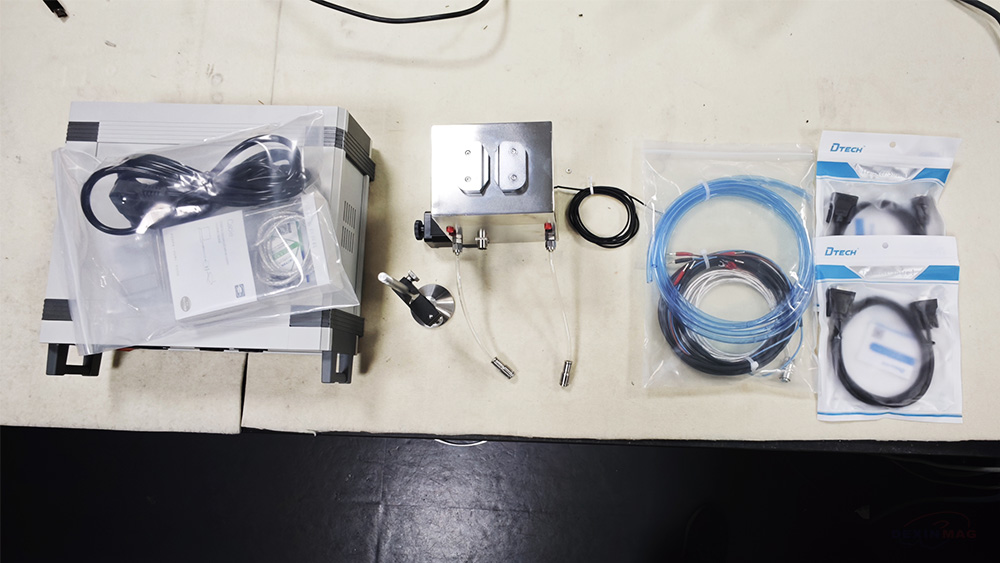
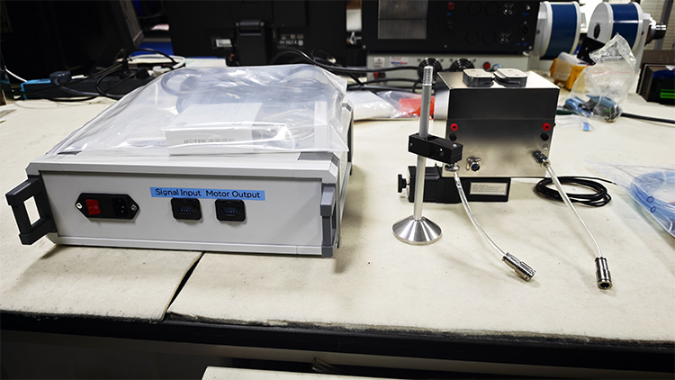
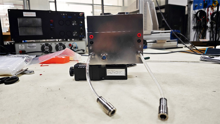
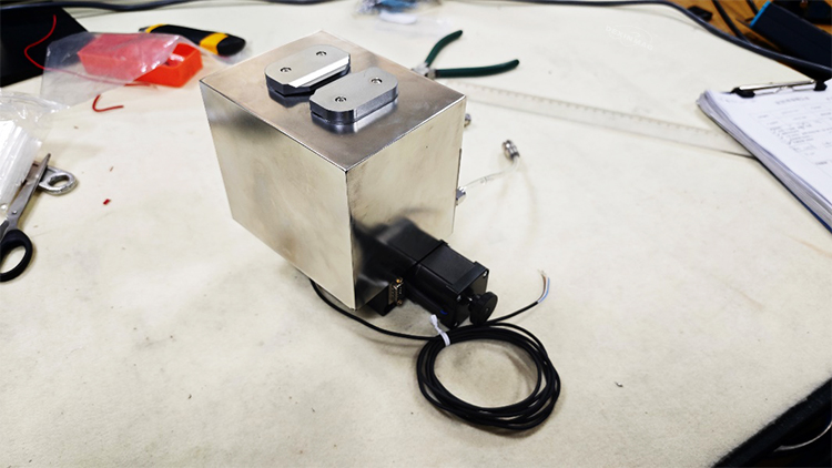
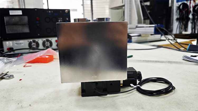
1. Mechanical Dimensions
Overall dimensions:
Length * Width * Height
190 mm * 120 mm * 180 mm
2. Packing List
| Name | Specifications | Quantity |
| Custom water-cooled electromagnet |
DXFGW2-05 |
1 |
| Power connection cable |
- |
2 |
| PT100 cable |
- |
1 |
| Series connection cable |
- |
1 |
| Water hose |
8*5 |
2 |
| Probe holder |
- |
1 |
| Certificate of conformity |
- |
1 |
| Test report |
- |
1 |
| Motor controller | ||
| Name | Specifications | Quantity |
| Serial cable |
RS485 |
1 |
| Serial cable | RS232 (female-to-female) |
2 |
| Controller power cable |
220V |
1 |
3. Packaging Type
Wooden packaging box
4. Packaging Filler
Foam board
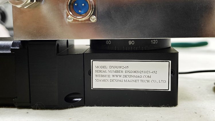
5. Labeling
Product Nameplate
6. Total Equipment Weight
7.528 kg
| Performance test report | |||||||
| Introduction | |||||||
| 1. Test purpose | |||||||
| Through the analysis of the test results, the evaluation of the product performance is obtained; Evaluate whether the test product meets the technical requirements; Provide reference data for product design and after-sales service, and provide a strong basis for leaving the factory. |
|||||||
| 2. Basic information | |||||||
| Product Name: Custom Water-Cooled Electromagnet |
Product model: | DXFGW2-05 | |||||
| Test time: | January 7, 2026 | ||||||
| 3. Testing environment | |||||||
| The detection environment is closer to the actual environmental conditions used by the user, including factors such as lead wire length and ambient temperature. The time is selected in the time interval where the fluctuation of the geomagnetic field is small. Before the test, the instruments required for the test were turned on and warmed up in advance and the measurement environment was recorded, as shown in Table 1. | |||||||
| Measurement environment | |||||||
| Environment temperature |
Product initial temperature |
Lead length | Environmental magnetic field |
||||
| 15.0℃ | 15.0℃ | - | 0~30000nT | ||||
| Table 1 Measurement environment data | |||||||
| Magnetic field parameter test | |||||||
| 1. Using the device | |||||||
| DX-F2031 power supply DX-180 Gauss Meter DXACP Power Amplifier |
|||||||
| 2. Magnetic field measurement | |||||||
| This product uses the following measurement methods: Fixed-point measurement: measure the magnetic field at the target point |
|||||||
| Magnetic field strength | |||||||
| No. | Display current (A) | Display voltage Voltage (V) | Magnetic field strength(mT) |
||||
| Custom Water-Cooled Electromagnet | 1 | 14.62 | 178.263 | ||||
| 2 | 29.33 | 321.12 | |||||
| 3 | 44.27 | 412.52 | |||||
| 4 | 59.57 | 464.58 | |||||
| 5 | 75.62 | 503.29 | |||||
| Table 2 Magnetic field strength data | |||||||
| Magnetic field uniformity | |||||||
| No. | Area | Current | Center(mT) | Max(mT) | Min(mT) | Uniformity | |
| #1 | 2*10*0.2mm | 1.5A | 259.567 | 263.499 | 249.11 | -4.0286% | |
| Coordinates | Magnetic field strength(mT) | ||||||
| (0,0,0) | 259.567 | ||||||
| (1,0,0) | 254.576 | ||||||
| (-1,0,0) | 254.276 | ||||||
| (0,5,0) | 258.95 | ||||||
| (0,-5,0) | 259.242 | ||||||
| (1,5,0) | 254.85 | ||||||
| (-1,-5,0) | 255.461 | ||||||
| (-1,5,0) | 252.82 | ||||||
| (1,-5,0) | 252.824 | ||||||
| (0,0,0.1) | 255.591 | ||||||
| (1,0,0.1) | 250.54 | ||||||
| (-1,0,0.1) | 250.784 | ||||||
| (0,5,0.1) | 255.02 | ||||||
| (0,-5,0.1) | 255.328 | ||||||
| (1,5,0.1) | 251.09 | ||||||
| (-1,-5,0.1) | 251.643 | ||||||
| (-1,5,0.1) | 249.11 | ||||||
| (1,-5,0.1) | 249.117 | ||||||
| (0,0,0.1) | 263.499 | ||||||
| (1,0,-0.1) | 258.032 | ||||||
| (-1,0,-0.1) | 258.399 | ||||||
| (0,5,-0.1) | 262.924 | ||||||
| (0,-5,-0.1) | 263.227 | ||||||
| (1,5,-0.1) | 258.696 | ||||||
| (-1,-5,-0.1) | 259.332 | ||||||
| (-1,5,-0.1) | 256.646 | ||||||
| (1,-5,-0.1) | 256.538 | ||||||
| Magnetic field uniformity | |||||||
| No. | Area | Current | Center(mT) | Max(mT) | Min(mT) | Uniformity | |
| #2 | 2*10*0.5mm | 1.5A | 259.567 | 269.729 | 243.705 | -6.1109% | |
| Coordinates | Magnetic field strength(mT) | ||||||
| (0,0,0) | 259.567 | ||||||
| (1,0,0) | 254.576 | ||||||
| (-1,0,0) | 254.276 | ||||||
| (0,5,0) | 258.95 | ||||||
| (0,-5,0) | 259.242 | ||||||
| (1,5,0) | 254.85 | ||||||
| (-1,-5,0) | 255.461 | ||||||
| (-1,5,0) | 252.82 | ||||||
| (1,-5,0) | 252.824 | ||||||
| (0,0,0.25) | 249.91 | ||||||
| (1,0,0.25) | 245.144 | ||||||
| (-1,0,0.25) | 245.285 | ||||||
| (0,5,0.25) | 249.364 | ||||||
| (0,-5,0.25) | 249.57 | ||||||
| (1,5,0.25) | 245.691 | ||||||
| (-1,-5,0.25) | 246.044 | ||||||
| (-1,5,0.25) | 243.705 | ||||||
| (1,-5,0.25) | 243.75 | ||||||
| (0,0,0.25) | 269.729 | ||||||
| (1,0,-0.25) | 263.945 | ||||||
| (-1,0,-0.25) | 264.378 | ||||||
| (0,5,-0.25) | 269.178 | ||||||
| (0,-5,-0.25) | 269.477 | ||||||
| (1,5,-0.25) | 264.726 | ||||||
| (-1,-5,-0.25) | 265.44 | ||||||
| (-1,5,-0.25) | 262.589 | ||||||
| (1,-5,-0.25) | 262.414 | ||||||
| Table 3 Uniformity data | |||||||
| Electrical parameter test | |||||||
| 1. Using equipment | |||||||
| Digital multimeter Impedance analyzer |
|||||||
| 2. Test method | |||||||
| The digital instrument with bridge circuit and voltammetry is used for measurement. The measurement results are shown in the table below. | |||||||
| Resistance R measurement | |||||||
| Environment temp | Product temperature | Measuring resistance | ResistanceR@20℃ | ResistanceR@85℃ | |||
| 15.0℃ | 15.0℃ | 14.140Ω | 14.473Ω | 18.800Ω | |||
| Table 4 Resistance R data | |||||||
| Temperature Rise Test | |||||||
| Testing Method | |||||||
| This product employs the following measurement methods: Maximum Current Temperature Rise Measurement: Measure the product's maximum safe operating time and highest temperature under the maximum current it can withstand; Measure the overall coil data regarding temperature, time, and current. The measurement results are shown in the table below. |
|||||||
| Temperature Rise Test | |||||||
| Operating current [A] | Operating time [min] | Product temperature [℃] | Product voltage [V] | ||||
| 5 | 0 | 12.7 | 69.78 | ||||
| 1 | 15.9 | 74.59 | |||||
| 2 | 21.2 | 77.82 | |||||
| 3 | 27 | 80.26 | |||||
| 4 | 32.3 | 82.27 | |||||
| 5 | 37.9 | 84.07 | |||||
| 6 | 43.2 | 85.7 | |||||
| 7 | 48.5 | 87.2 | |||||
| 8 | 53.3 | 88.7 | |||||
| 9 | 58.1 | 90.08 | |||||
| 10 | 62.8 | 91.49 | |||||
| 11 | 66.9 | 92.64 | |||||
| 12 | 70.9 | 93.75 | |||||
| 13 | 74.8 | 94.8 | |||||
| 14 | 78.8 | 95.78 | |||||
| 15 | 82.6 | 96.65 | |||||
| Table 5: Relationship between temperature, operating time, and current. | |||||||
| Conclusion | |||||||
| The magnetic field and electrical performance of the product meet the requirements of the corresponding technical parameters. The final performance of the product is subject to this document. | |||||||

