


Magnet Inserting Machine for Motors
Working Principle
1. A flexible magnetic strip is manually placed flat in the material loading slot.
2. An iron shell is placed in the positioning nest of the insertion die.
3. After the operator triggers the start switch, the machine automatically performs the following sequence:
- Push blade advances → pushes the magnetic strip into the circular die cavity
- Push blade retracts
- Upper cylinder descends → presses the iron shell downward
- Top punch (core) extends downward → forces the magnetic strip fully into the shell
- Top punch retracts
- Upper cylinder rises
4. The operator removes the finished product and starts the next cycle.
All movements are controlled by pneumatic cylinders.
Main Technical Specifications
1. Power supply: AC 220 V ±10%, 50 Hz
2. Current consumption: ≈ 1 A
3. Operating air pressure: 8 bar (kg/cm²)
4. Cycle time: ≤ 2.0 S/Pcs (depending on settings)
5. Applicable iron shell diameter range: Ø22.8 mm – Ø68 mm
6. Operating ambient temperature: -10 °C to +48 °C
7. Altitude: ≤ 1000 m
8. Relative humidity: ≤ 95% (at 25 °C, non-condensing)
9. Machine dimensions (L × W × H): approx. 550 × 705 × 500 mm
10. Net weight: approx. 30 kg
Safety Precautions
1. Read all safety instructions before operation.
2. Always keep hands clear of the die area when triggering the machine.
3. Recommended safe operating posture: left hand places shell → right hand triggers → left hand must be completely away from the press cylinder before triggering.
4. Never reach into the machine while power or air is on.
5. High voltage (220 V) exists inside the electrical enclosure — only qualified personnel may open it and adjust timers.
6. Ensure the machine is properly grounded before connecting power.
7. Do not operate the machine if any safety guard is removed or damaged.
8. Keep the machine surface clean and the electrical cabinet dry.
9. Avoid touching moving parts (cylinders, push blade) during operation.
10. Do not transport or store the machine upside down, tilted, or subject to strong vibration.
Preparation Before Use
1. Place the machine on a stable, level workbench.
2. Connect to AC 220 V power supply (ensure reliable grounding).
3. Connect the compressed air hose and adjust the regulator to 8 bar.
4. Confirm no air leaks.
5. Turn on the power switch.
6. Check that all manual push-button functions respond correctly during dry-run testing.
Operation Instructions – Automatic Mode
1. Manually place the flexible magnetic strip flat and straight in the loading slot.
2. Place the iron shell flat and centered in the die positioning nest.
3. Confirm both hands are in safe positions (left hand away from die area).
4. Press the trigger switch (foot pedal or two-hand control) to start the automatic cycle.
5. After the cycle finishes (upper cylinder rises), remove the finished product.
6. Repeat from step 1.
Manual Debugging Mode (for die change or initial setup)
Use the manual push-buttons only during setup, troubleshooting, or die change:
- Push strip manual button: advances the push blade to feed strip into die (observe position)
- Press shell manual button: lowers the upper cylinder to hold shell
- Insert strip manual button: extends the top punch to insert strip
Typical debugging sequence:
1. Press and hold “Push strip” → observe strip enters die correctly → release
2. Press and hold “Press shell” (do not release)
3. Press and hold “Top strip” for ≈2 seconds → observe full insertion → release both buttons
4. Visually check result
5. Adjust timers if necessary, then test full automatic cycle
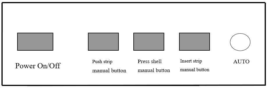
Panel diagram
Timer Adjustment (performed with enclosure open – qualified personnel only)
Four independent time relays control the sequence:
1. Push strip dwell time: how long the blade stays forward after reaching end position
2. Delay before press shell: time between push blade retract and cylinder descent
3. Press/hold time: duration the upper cylinder stays down (usually short – just enough to stabilize shell)
4. Top insert dwell time: how long the top punch stays extended
Adjustment guideline:
Start with short times → gradually increase only as needed according to product size and magnet stiffness. Over-long times reduce cycle speed unnecessarily.
Die (Mold) Replacement Procedure
1. Turn off power and disconnect air supply.
2. Using an Allen key, remove the current insertion die, core/punch blade, and push blade guide.
3. Install the new die set:
- Mount and tighten the core/punch first
- Install insertion die
- Install push blade and guide rail
- Align push blade guide with die strip entrance (three-point alignment)
- Tighten all screws
4. Manually move the push blade guide left/right to confirm smooth sliding without binding.
5. Reconnect air and power.
6. Perform manual debugging (section 7) before switching to automatic mode.
Maintenance & Daily Checks
1. Keep die, push blade, and guide rail clean (no magnetic debris buildup)
2. Regularly check air filter/water separator and drain if necessary
3. Inspect pneumatic tubing for cracks or leaks
4. Check that all screws on die and moving parts remain tight
5. Store machine in a dry environment when not in use
You may also like
It is mainly used in the production of permanent magnet DC motors, small DC motors, and similar products that require a magnetic ring/arc segment to be precisely inserted into a metal housing.
The machine combines pneumatic pressing and mechanical pushing actions to complete the insertion process in one automatic cycle after triggering.
