


High Vacuum Magnetron Sputtering Coating System
Basic Structure and Main Technical Specifications of the Equipment
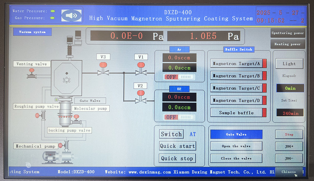
User interface of DXZD-400 High Vacuum Magnetron Sputtering Coating System
The coating equipment consists of a vacuum chamber, evaporation source system, sample stage system, vacuum pump unit, film thickness detection system, equipment frame, electrical control system, and glovebox system. The front door of the vacuum chamber can be connected to the glovebox, adopting an integrated design. The whole equipment has a compact structure and a simple layout, avoiding the cluttered appearance of experimental equipment.
1. Vacuum Chamber: 1 set
1) Appearance: One set of high-quality 304 stainless steel square vacuum chamber with front and rear opening doors. The internal dimensions are 420*360*H520mm. The rear door is a hinged square door for easy cleaning, vacuum chamber adjustment, maintenance, and handling of items. The front door is a sliding square door. Both front and rear doors are equipped with DN100 windows.
2) Bottom: 4 metal source interfaces, 2 U.S. MCVAC water-cooled film thickness probe interfaces, 2 CF25 lighting interfaces.
3) Top: 1 sample stage interface, 2 pneumatic baffle interfaces, 1 GDQ-J16B-KF high vacuum pneumatic baffle valve interface.
4) Sidewall: 1 JTFB-650Z water-cooled grease-lubricated molecular pump interface, 1 JCDQ-J40B-CF high vacuum pneumatic baffle valve interface, several reserved flanges.
5) Chamber Leak Rate: Overall leak rate better than 5×10⁻⁸ Pa·m³/s, pressure maintained for 12 hours, pressure below 10 Pa.
2. Evaporation Source System: 1 set
1) 4 metal sources: 4 sets of water-cooled copper electrodes, compatible with evaporation boats (tungsten, molybdenum, tantalum boats) and spiral filaments. It can evaporate metals and oxides. Equipped with pneumatic baffles, flip switches, 2 DC power supplies, digital display. The evaporation power supply can be controlled by software or manually, and it can also be automatically adjusted through the 310 film thickness monitor with PID (closed-loop control) for single-channel evaporation rate adjustment.
2) Partition: The evaporation source is separated by partitions to avoid cross-contamination. Some partitions can be removed without tools.
3. Sample Stage System: 1 set
1) Substrate rotation: Sealed with magnetic fluid to ensure sealing reliability. Rotation speed: 5-20 rpm, continuously adjustable via touch screen.
2) Substrate lifting: The distance between the substrate and the evaporation source is 240-340mm, electrically lifted and continuously adjustable via touch screen.
3) Substrate holder: Armored wire heating with a maximum heating temperature of 300°C. The 130*130mm substrate tray can hold 25 pieces of 15*15mm substrates.
4) Power supply: 1 DC power supply.
5) Substrate baffle: Sealed with magnetic fluid, it can block or open at any rotation angle of the substrate. Controlled by software, the rotation switch operates smoothly.
4. Vacuum Pump Unit: 1 set
1) VRD-30 two-stage pump: 1 unit.
2) DDC-JQ40-KF vacuum solenoid inflation valve: 1 unit.
3) KF40 pump valve connection hose: 1 set.
4) GDQ-J40B-KF high vacuum pneumatic baffle valve: 1 unit.
5) JTFB-650Z water-cooled grease-lubricated molecular pump: 1 unit.
6) CCQ-150CF pneumatic ultra-high vacuum gate valve: 1 unit.
7) CDQ-J40B-CF ultra-high vacuum pneumatic baffle valve: 1 unit.
8) GDQ-J16B-KF high vacuum pneumatic baffle valve: 1 unit.
9) ZDF-5227 digital vacuum gauge: 1 unit (measurement range: 1×10⁵–1×10⁻⁸ Pa).
5. Film Thickness Detection System: 1 set
1) Film Thickness Monitor: 1 U.S. INFICON SQC310 quartz crystal film thickness monitor, Mode: Sequential deposition. Probe: 2 channels. Display and control accuracy: 0.01Å/s, frequency resolution: 0.01Hz, with PID function for automatic control of deposition rate via single channel.
2) Film Thickness Probes: 2 imported U.S. MCVAC water-cooled film thickness probes, 6MHz, with quick-lock structure for crystal oscillator replacement, avoiding damage from threaded tightening structures. Sealed with an O-ring locking structure.
6. Equipment Frame: 1 set
1) 1 set of 40 carbon steel square tube welded frame, surface coated.
2) 4 sets of 3-inch universal wheels for movement and adjustment.
3) 4 sets of M16 anchor bolts for locking and positioning.
7. Other Electrical Control System:
1 set (Electrical control integrated within the equipment frame)
1) Baking and lighting power supply: 1 unit.
2) Main control power supply: 1 unit, equipped with a 10-inch touch screen, PLC controller, sample stage and baffle controller, evaporation source baffle controller, pump valve switch, phase sequence detection, and cable switch connectors.
8. Other Technical Parameters:
1) Phase loss protection, misoperation protection, interlock, and one-button vacuum start/stop functions.
2) Power supply: ~220V single-phase system (peak power 3KW).
3) Water supply: Circulating cooling water system, cooling water temperature: 17°C–35°C, operating environment temperature: 10°C–40°C.
4) Air supply: Small oil-free silent air pump providing 0.2–0.3MPa pressure for driving pneumatic valves.
Ultimate vacuum: Better than 6×10⁻⁵ Pa, time from atmospheric pressure to 6×10⁻⁴ Pa less than 35 minutes, dry nitrogen filling.
Glove Box System: 1 Set
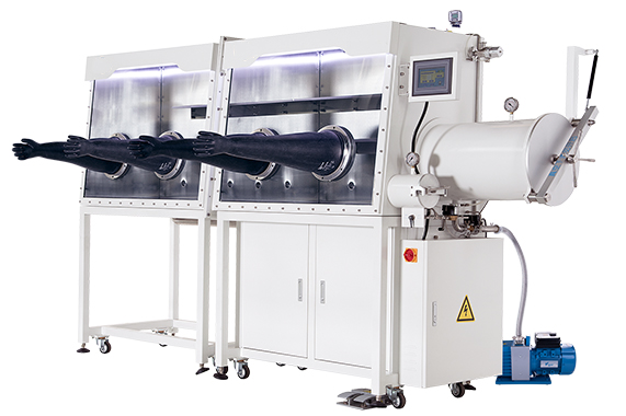
Box
1. Two-section glove box body with internal dimensions of 1200mm (L) x 300mm (W) x 900mm (H). The rear of the box connects to the vacuum coating machine, with dimensions of 1200mm (L) x 750mm (W) x 900mm (H). The box material is SUS304 stainless steel, 3mm thick, with a white-painted exterior and brushed metal interior.
2. Two removable safety tempered glass windows, approximately 8mm thick, with a slanted design for the operating surface.
3. Four aluminum alloy glove ports, machined from solid rods, anodized, and corrosion-resistant.
4. Four butyl rubber gloves.
5. Several KF40 standard interfaces reserved at the rear of the box.
6. Three stainless steel shelves inside the box, removable and adjustable in height.
7. Safety valve to protect the equipment and materials inside the glove box.
8. Steel support frame, 900mm high, equipped with universal wheels for leveling, mobility, and fixing.
9. LED white light for box illumination, installed at the front top of the glass window.
Transfer Chambers
1. Large transfer chamber:
- Material: SUS304 stainless steel, 3mm thick.
- Dimensions: Φ370mm x 800mm.
- Position: Right side of the box.
- Connection: Removable, with a professional flange seal connection.
- Transfer method: Using a movable tray, detachable for easy transfer of large materials.
- Operation:
- Manual operation via touch screen.
- Automatic operation with vacuuming and gas filling functions. Users can set the number of cycles, vacuum time, and filling pressure. The PLC automatically completes multiple vacuum-filling operations.
2. Small transfer chamber:
- Material: SUS304 stainless steel, 3mm thick.
- Dimensions: Φ150mm x 300mm.
- Position: Right side of the box.
- Connection: Sealed by welding.
- Transfer method: Using a movable tray.
- Operation: Manual operation via a three-way ball valve.
Gas Purification System
1. Gas purification column:
- Uses high-performance copper catalyst and molecular sieve for moisture and oxygen removal.
- Oxygen and moisture adsorption capacity: 60 liters and 2 kg, respectively.
2. Regeneration of the purification column is done using a hydrogen/nitrogen or argon mixture.
- Regeneration gas: Hydrogen/nitrogen mixture (H2: 5%, N2: 95%).
- Due to the ultra-low leakage rate, the regeneration frequency is about once a year.
3. Circulation fan:
- Flow rate: 60m³/h. The glove box has automatic and manual circulation modes, with low energy consumption, typically under 50W. No external frequency converter or chiller required.
- Installed in a sealed stainless steel container with full welding for good sealing.
- Controlled by an oxygen-water analyzer, the fan runs only about 5 minutes per hour, reducing heat generation and eliminating the need for water cooling, thus extending the fan's lifespan.
4. Organic solvent adsorption column with activated carbon adsorption material, replaced when saturated.
5. Electro-pneumatically controlled main circulation valve with KF40 standard interfaces.
6. All gas circuits are solenoid-valve-controlled, and the regeneration of the purification column is fully automated.
7. Gas filters are installed at the inlet and outlet of the circulation system.
Control System
1. Control system consists of Siemens PLC and a 7-inch color touch screen, with a user-friendly Chinese/English interface.
2. Control functions:
- Automatic control of box pressure: Users can set the working pressure range between +10 to -10 mbar. The default range is 0 to +5 mbar. If the pressure exceeds 12 mbar, the PLC automatically opens the safety valve to release pressure.
- Single-button operation for multiple vacuum-filling cycles in the transfer chamber.
- Circulation purification automatically controlled by water and oxygen levels inside the box.
- Manual or automatic leak rate monitoring: The PLC can detect and report the box’s leak rate daily or on-demand.
- Automatic gas cleaning: Users can set the cleaning time and start the process via the touch screen.
- Historical data is recorded and can be exported via USB.
- The system alerts users of operation errors and unsafe conditions.
- All operations are interlocked to avoid damage to the equipment or contamination of the atmosphere inside the box.
Other Accessories
1. Vacuum pump: UK EDWARDS brand, model RV12, flow rate 12m³/h, ultimate vacuum 2x10⁻³ mbar, equipped with an imported oil mist filter.
2. Oxygen analyzer:
- Brand: US Panametrics.
- Measuring range: 0-10, 100, 1000, 10000 ppm.
- Accuracy: 1% of the range or 0.2ppm.
- Continuously monitors oxygen levels inside the box.
3. Water analyzer:
- Brand: UK Michell.
- Measurement range: 20°C to -100°C (dew point).
- Accuracy: ±2°C.
4. Power outlets inside the box with a multi-socket extension.
5. Temperature control system: Controls internal temperature between 22°C and 25°C.
Configuration
|
No. |
Name |
Specifications |
Units |
Q’ty |
Remarks |
|
Vacuum Chamber |
|||||
|
1 |
Vacuum Chamber |
420×360×H520mm |
Set |
1 |
|
|
2 |
Rear Door of Vacuum Chamber |
Hinged, with single window |
Set |
1 |
|
|
3 |
Front Door of Vacuum Chamber |
Horizontal sliding, with single window |
Set |
1 |
|
|
Evaporation Source System |
|||||
|
1 |
Metal Source |
Pneumatic shutter |
Set |
4 |
|
|
2 |
Metal Source Power Supply |
|
Set |
2 |
|
|
Sample Stage System |
|||||
|
1 |
Sample Stage Assembly |
|
Set |
1 |
|
|
2 |
Sample Stage Shutter |
|
Set |
1 |
|
|
3 |
DC Power Supply |
|
Set |
1 |
|
|
Vacuum Pump Unit |
|||||
|
1 |
Two-stage Pump |
Model: VRD-30 |
Unit |
1 |
|
|
2 |
Vacuum Electromagnetic Gas Valve |
Unit |
1 |
|
|
|
3 |
Vacuum Pump Connection Pipeline |
Set |
1 |
|
|
|
4 |
High Vacuum Pneumatic Shutter Valve |
Unit |
1 |
|
|
|
5 |
Water-cooled Grease-lubricated Molecular Pump |
Unit |
1 |
|
|
|
6 |
Pneumatic Ultra-high Vacuum Gate Valve |
Unit |
1 |
|
|
|
7 |
Ultra-high Vacuum Pneumatic Shutter Valve |
Unit |
1 |
|
|
|
8 |
High Vacuum Pneumatic Shutter Valve |
Unit |
1 |
|
|
|
9 |
Digital Vacuum Gauge |
Model: ZDF-5227, one high, one low |
Set |
1 |
|
|
Film Thickness Monitoring System |
|||||
|
1 |
Quartz Crystal Film Thickness Monitor |
USA INFICON SQC310 |
Set |
1 |
|
|
2 |
Imported Water-cooled Film Thickness Sensor |
USA MCVAC, accessories: includes oscillator package, etc. |
Set |
2 |
|
|
Equipment Rack |
|||||
|
1 |
Main Rack |
|
Set |
1 |
|
|
2 |
Small Refrigeration Water Chiller |
|
Set |
1 |
|
|
3 |
Small Oil-free Silent Air Pump |
|
Set |
1 |
|
|
Electrical Control System |
|||||
|
1 |
Heating and Lighting System |
|
Set |
1 |
|
|
2 |
Heating and Lighting Power Supply |
|
Unit |
1 |
|
|
3 |
Main Control Power Supply |
|
Set |
1 |
|
|
Electric control system |
|||||
|
1 |
Glove Box System |
2400/750/900 |
Set |
1 |
|
